A quick overview how the method (monitor animals using transmitters) works:
General information about locating animals
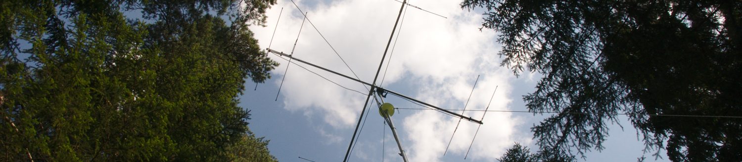
To generate a movement profile, you need to setup a system with several receivers, antennas and masts depending on your study requirements. There is a simple rule: the more receivers – the more precision – the more time it takes to setup the system. We will call a location with several antennas on one mast a station.
Signal Reception
When the system is up and running the receivers log the signals within up to 1 MHz Frequency Range with all their details like:
- Time and Date
- Frequency
- Signal Strength
- Signal Length
- Band Width
The algorithm performs a FFT (spectogram) and identifies peaks in the power spectrum.
Collect the Data
The data is always stored in local csv-files which are easy and convenient to read. Additionally the data can be saved in a local or remote MySQL database. The database is more convenient if you want to monitor the animal's positions in real time. All the stations can be accessed remotely using the 2G/3G/4G Network.
If no connections are possible or if live data isn't necessary, then the csv files can be collected afterwards and combined with all the other information like antennas orientations and locations using a web application (shiny).
Just a word: Localization
There are several options on how you can find the animal's location using radio transmitters. The possibility to use GPS-trackers won't be discussed since the weight is too high if they transmit the position. In our project we are using the 3rd of the following options, as it is the simplest to implement.
There are three possible ways to calculate the animal’s position:
- Time Difference of Arrival (TDOA): An electromagnetic wave travels with the speed of light, which means that depending of the distances between the transmitter and the receivers it takes different times till the signal is received. This can be used to calculate the exact position of the transmitter.
- The phase of the electromagnetic wave can be used. The incoming wave will be received with several antennas which have a known distance to each other. If you take a look at the phase difference of the incoming signal on the different antennas, you can calculate the origin's direction of the wave. Taking the bearings from several positions, the transmitters location can be derived as the intersection of two lines.
- Directional Antennas have a preferred amplification direction. If the antenna is targeted directly on the transmitter, the signal strength of that direction will be highest. If several directional antennas are taken, the direction of the origin can be calculated. Taking again the bearings from several positions, the location can be derived.
Bearings
From the above-mentioned three ways to get the animal's position, we are focusing on an automation of the triangulation technique using the difference in signal strength. The basic idea is to receive a signal on at least two directional antennas which are next to each other on the same station. From the difference in signal strength on both antennas, combined with the simulated antenna patterns, the bearing of the emitter relative to the mast can be calculated.
An example: you got a setup with 4 antennas on one mast (one north – one east – one south – one west) and receive a good signal on the northbound antenna. To derive a bearing you'll need a signal at either the west- or eastbound antenna as well. Then the signal strength on those antennas are compared. If it is the same on both antennas (and the antennas are of the same type), the transmitter must be in the middle of those two antennas (example: antenna 1: north 0° – antenna 2: east 90°- transmitter: 45°). This ends in a mathematical equation using the simulated antenna patterns (angle vs gain).
A crucial step hasn't been mentioned yet – each set of receiver and antenna must be calibrated. Every receiver, plug, cable and antenna contributes to the recorded signal strength. By comparing the signal strength between different receivers we have to account for those effects, otherwise the bearing will be calculated with an error.
Triangulation
The final step is to triangulate the position of the transmitter. To do so we need at least two bearings from different stations. Then we calculate the intersection which is an approximation for the transmitter's (and thus the animal's) position.